360° motorcycle stand — GSXF
A detachable tripod system designed to mount a 360° camera on the rear luggage rack of a GSXF motorcycle — engineered for stability, quick assembly, and safety-driven detachment in case of impact.
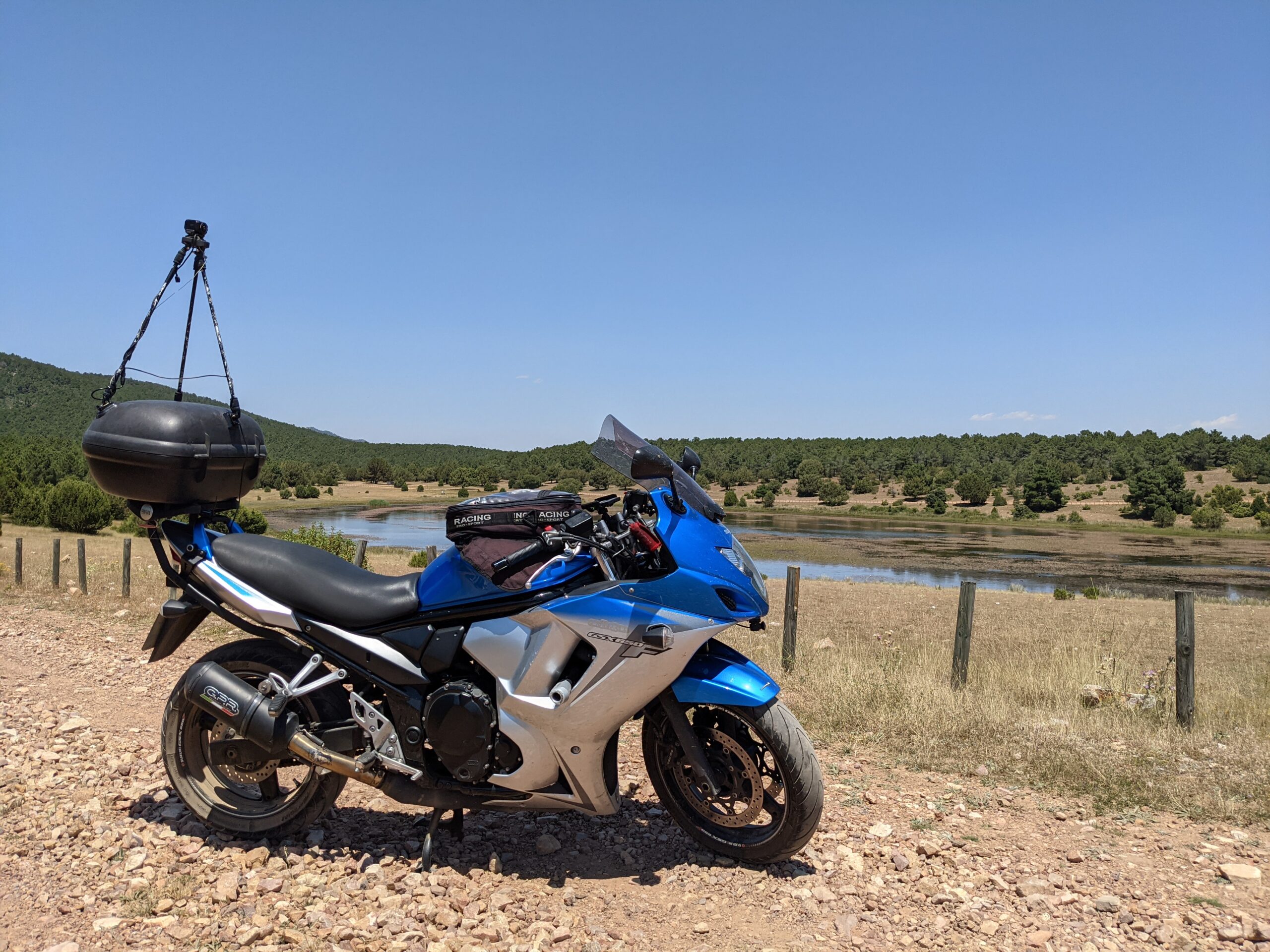
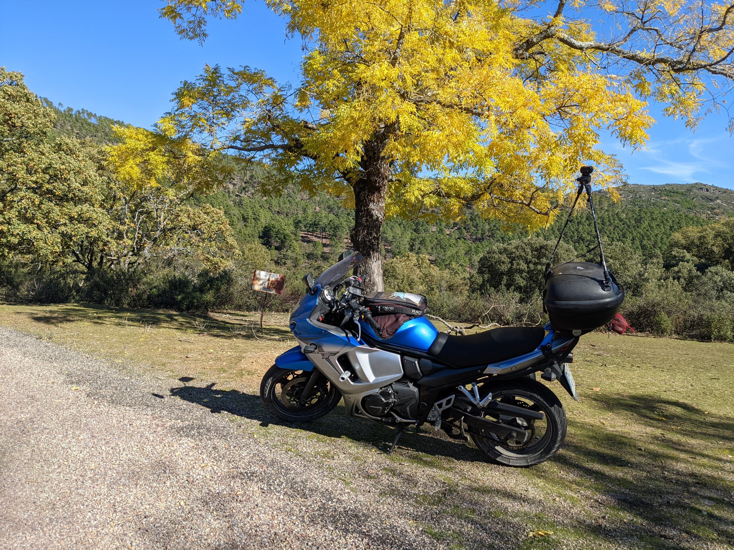
I’m excited to present an innovative detachable tripod specifically designed for motorcycles. The system mounts onto the rear luggage rack and provides a secure platform to install a 360° camera, enabling immersive recordings of your rides from every angle.
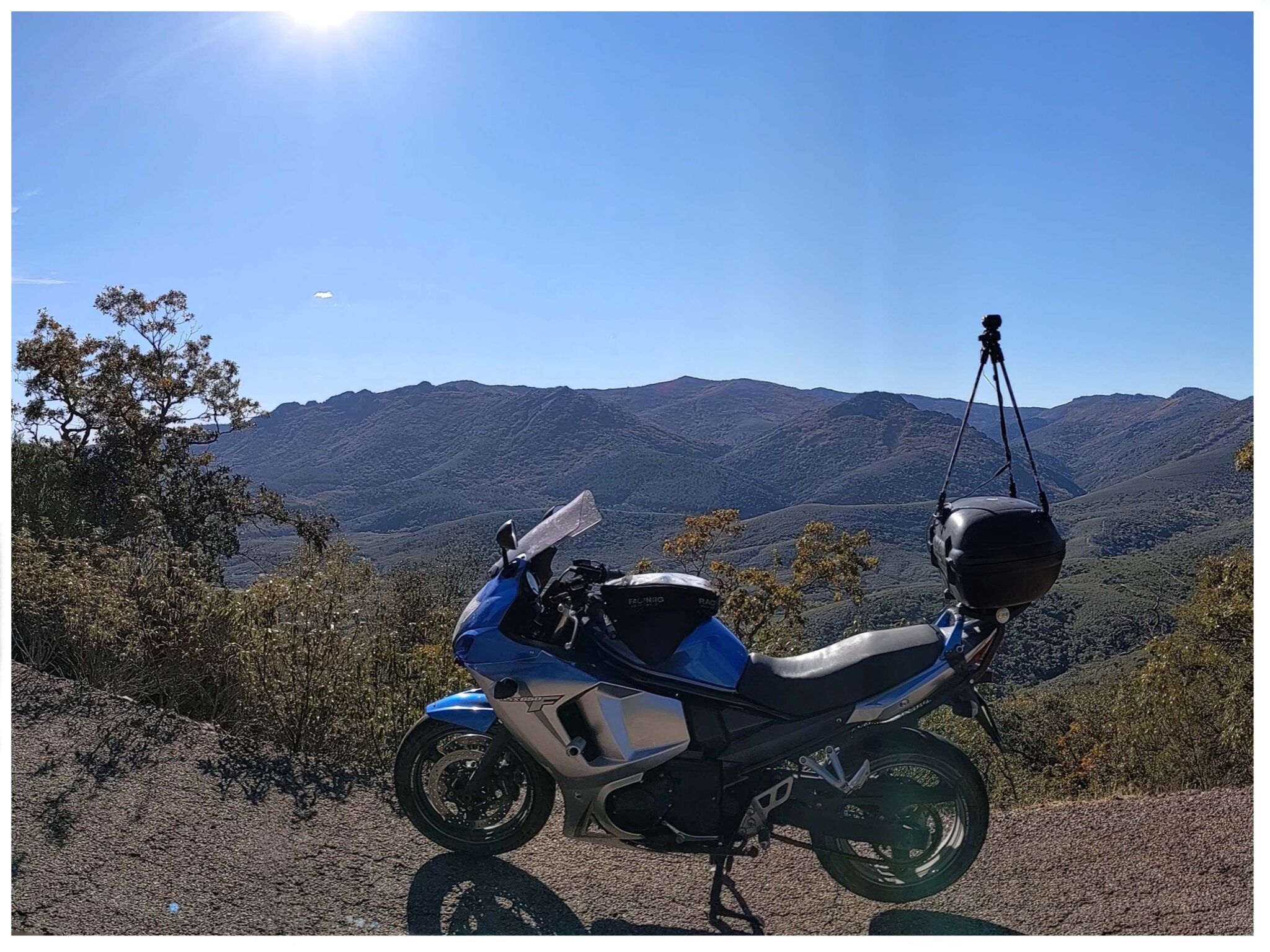
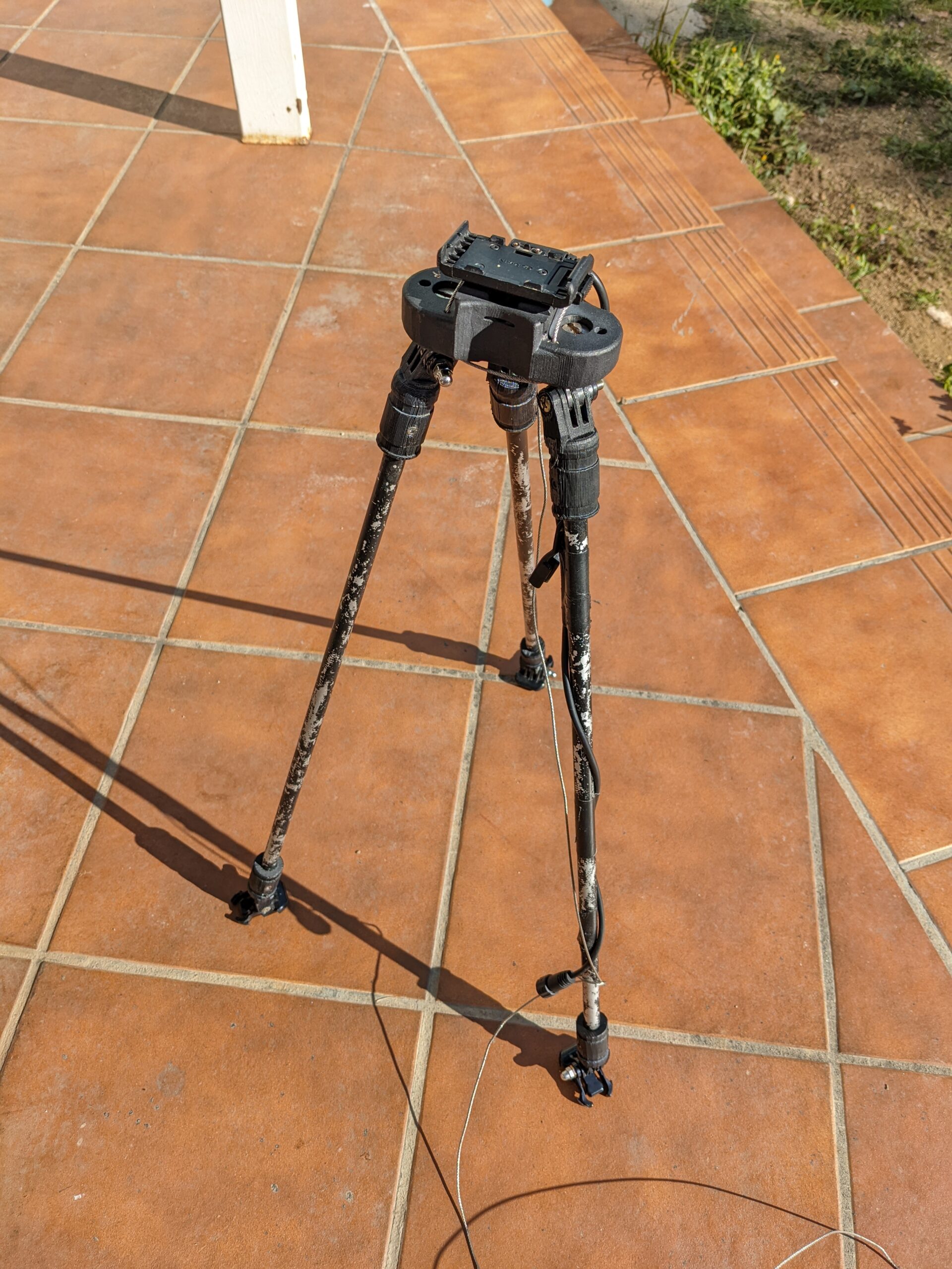
The tripod is built using 3D-printed components combined with sturdy aluminum rods, creating a robust assembly that remains practical for real use. It can be disassembled in about 5 minutes, making it ideal for on-the-go adventurers.
What sets this design apart is the non-permanent mounting system. The device is designed to detach in case of an accident, prioritizing rider safety and reducing the chance of rigid parts becoming a hazard.
After conducting initial printing tests at home, I moved to professional laser printing to guarantee safety, precision, and durability. The system has undergone extensive real-world testing, proving long-lasting performance under typical riding conditions.
Structure analysis
To ensure safety and stability, I analyzed the forces the tripod must withstand at each attachment point to the luggage rack and at the camera itself. The tripod is composed of three 50 cm aluminum legs, arranged at roughly 30° with respect to each other. The camera (≈160 g) is installed at the tip, and the system is intended for riding up to 120 km/h while respecting supported G-force constraints.
Key forces considered at the luggage rack attachment points: vertical (weight), lateral (movement / wind), and dynamic (accel / brake / turning). At the camera tip, we also account for gravitational load and vibration transmission.
| Variable | Description | Formula |
|---|---|---|
| W | Weight of the camera | W = m * g |
| α | Angle of inclination | (depends on motorcycle position) |
| v | Motorcycle velocity | (depends on speed) |
| r | Radius of curvature | (depends on the curve) |
| F_c | Centripetal force | F_c = (m_total * v^2) / r |
| F” | Updated general force | F” = F’ + F_c |
| F_system” | Total force on the system | F_system” = F” + W |
| F_leg” | Force on each leg | F_leg” = F_system” / 3 |
| θ | Angle with vertical axis | θ = 360° / 3 |
| Fv” | Vertical force on each leg | Fv” = F_leg” * cos(120°) |
| Fh” | Horizontal force on each leg | Fh” = F_leg” * sin(120°) |
In the calculations, m_total represents the total mass of the system: camera + tripod + mounting hardware. This ensures centripetal force is calculated correctly during turns, reflecting real operating conditions.
| Velocity (km/h) | Inclination (°) | Radius (m) | F_leg” (N) | Fv” (N) | Fh” (N) |
|---|---|---|---|---|---|
| 30 | 0 | 100 | 6.74 | 3.37 | -5.84 |
| 30 | 0 | 200 | 3.62 | 1.81 | -3.13 |
| 30 | 10 | 100 | 6.74 | 2.24 | -6.03 |
| 45 | 0 | 100 | 15.36 | 7.68 | -13.27 |
| 45 | 20 | 300 | 8.25 | 2.06 | -8.06 |
| 60 | 0 | 400 | 5.43 | 2.71 | -4.69 |
| 75 | 30 | 500 | 8.65 | 1.73 | -8.05 |
| 90 | 0 | 600 | 4.06 | 2.03 | -3.50 |
| 90 | 40 | 700 | 6.77 | 0.90 | -6.62 |
| 105 | 0 | 800 | 3.19 | 1.60 | -2.75 |
| 120 | 0 | 900 | 2.56 | 1.28 | -2.21 |
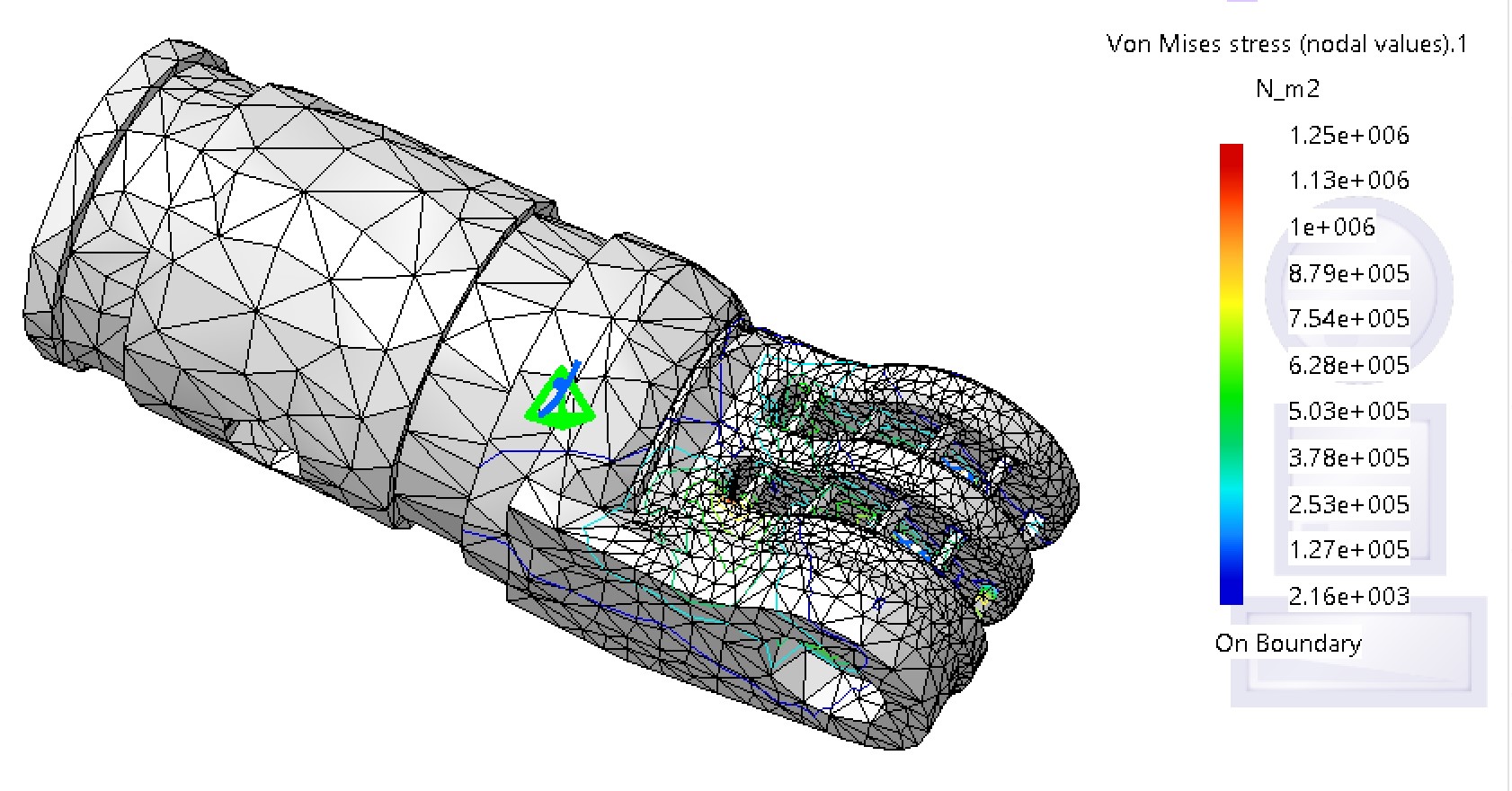
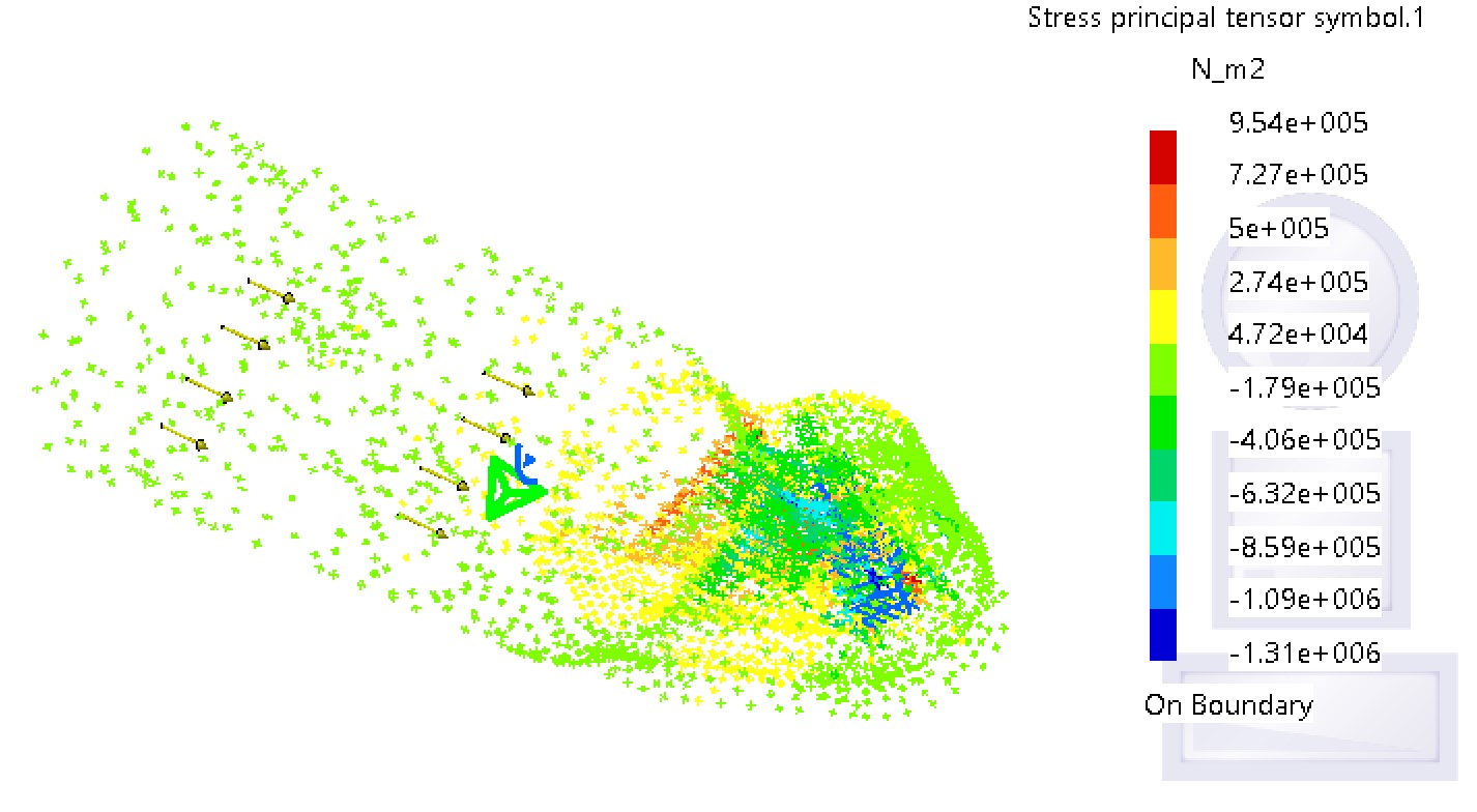
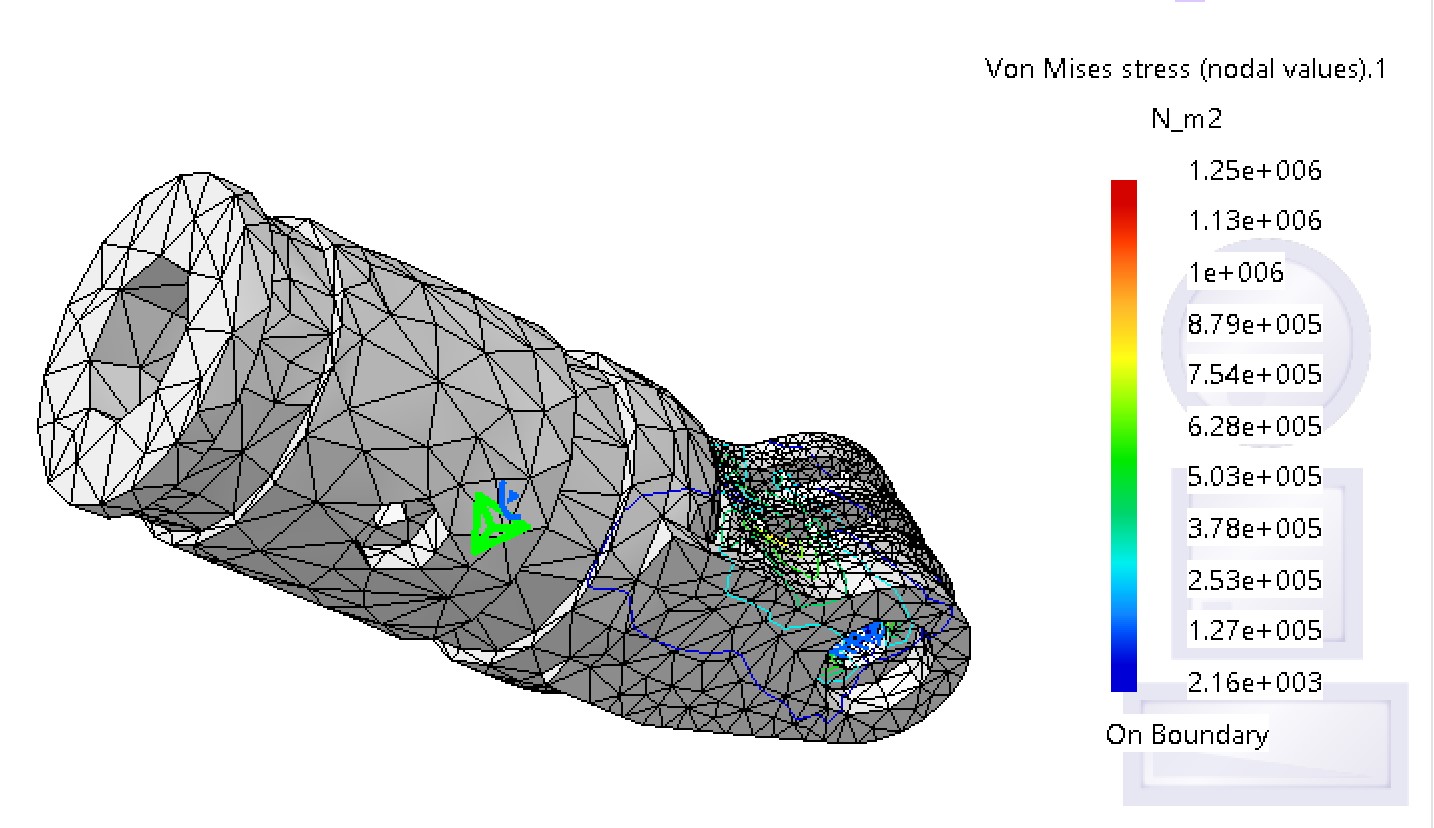
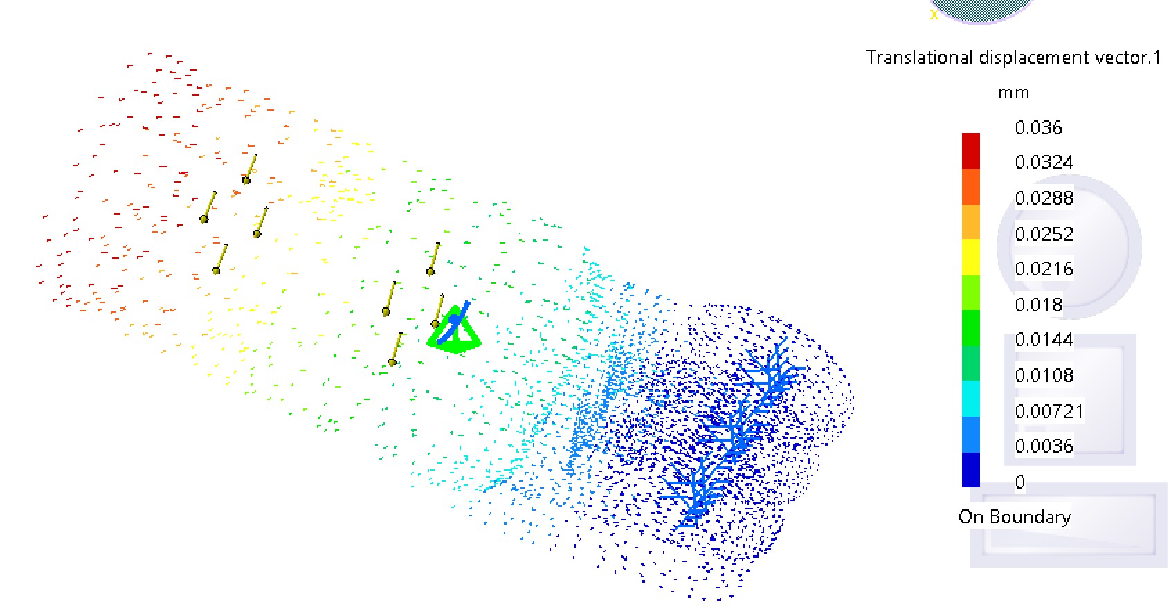
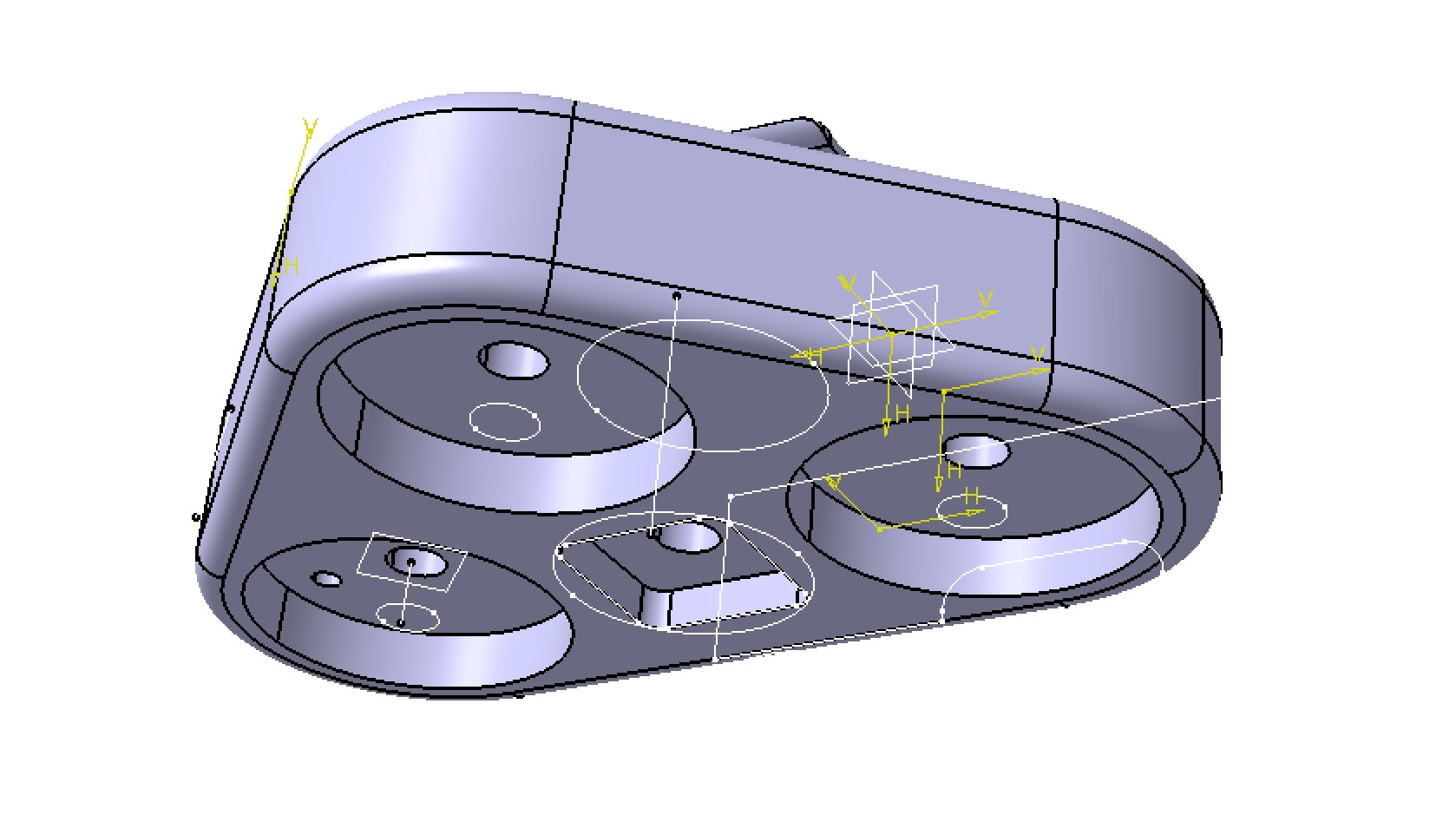
Software analysis of structure
Beyond the physical design, a software-based structural analysis was conducted for critical areas such as the tripod head and base. Below are key reference files used in the analysis process.
Snapshot structure
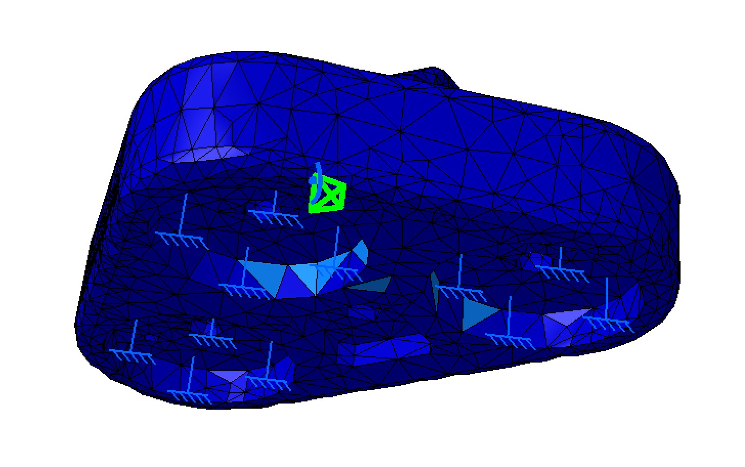
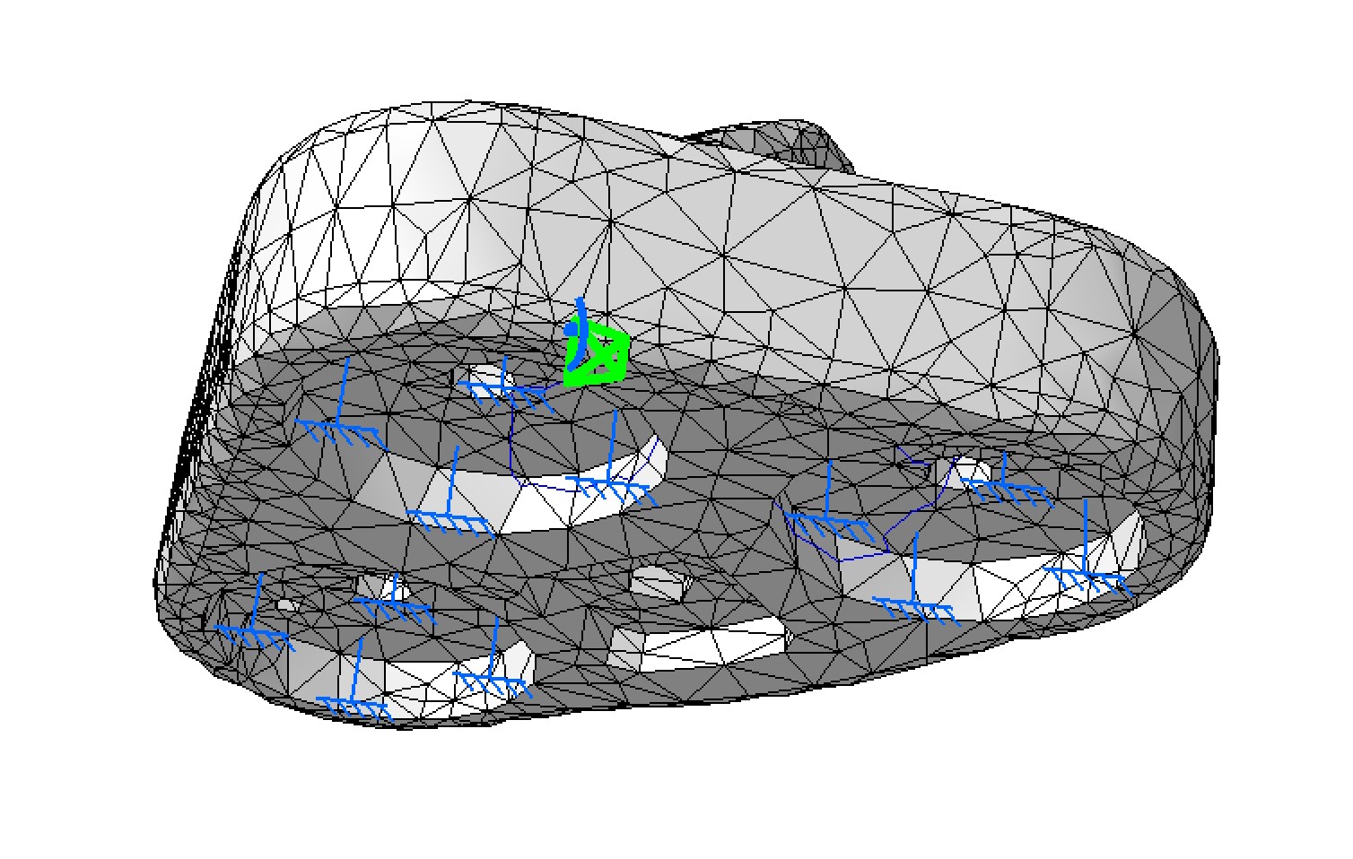
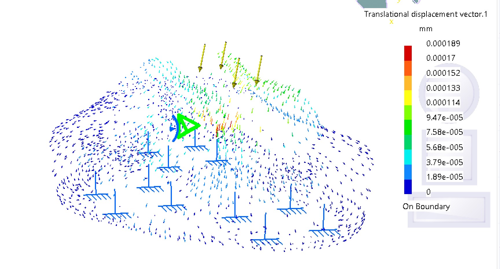
Advance structure analisys